Entity-Relationship Fundamentals
Before a single table is created or query written, every database begins as a diagram on a whiteboard. The Entity-Relationship (ER) model is that diagram—the visual language that transforms "we need to track trainees and courses" into a precise blueprint that both stakeholders and developers can understand and refine together.
How We Model Reality: The Entity-Relationship Model
Designing a database begins with understanding the world we intend to capture—the people, objects, and their interconnections. The Entity-Relationship (ER) Model¹ ¹ The ER Model was introduced by Peter Chen in his seminal 1976 paper "The Entity-Relationship Model: Toward a Unified View of Data." It remains the foundation of database design today. provides the visual language for this first, crucial stage. Think of it as the blueprint for a database, analogous to how a UML class diagram serves as a blueprint for a software system. It transforms user requirements, which are typically described in words, into a structured, visual format that bridges the gap between non-technical users and technical designers.

Understanding the Blueprint's Core Components
The power of the ER model lies in its simplicity. It uses just three fundamental concepts to model complex real-world scenarios: entities, attributes, and relationships. This minimalism allows for clarity in the initial conceptual design, where the primary goal is accurate representation, not implementation details.
Entities and Their Types: The "What" of the Database
An entity is any distinct object in the real world that we want to record information about. In user requirements, entities are typically the nouns—like a specific trainee named Raju, a particular vehicle, or a booking. The collection of all similar entities is defined by an entity type, which is the schema or template. For example, `TRAINEE` is an entity type, while individual trainees like (26, Priya, ...) are entity instances. This distinction is critical: ER diagrams visually represent entity types (the categories), not the multitude of individual entity instances (the specific members of those categories).
This separation mirrors the common computer science concept of type versus instance. The entity type is the intention—the definition of what a `TRAINEE` is. The set of all actual `TRAINEE` entities is the extension—the data itself. By focusing on types in the diagram, we create a clean, scalable model independent of the volume of data.
Attributes: The "Details" of an Entity
An attribute is a property that describes an entity. If entities are the nouns, attributes are the descriptive nouns that qualify them. For a `TRAINEE` entity type, relevant attributes could be `name`, `age`, `address`, and `phone number`. Attributes fill in the details, turning a generic category like "trainee" into a recordable data profile.
Relationships: The "How" Entities Connect
A relationship is an association among two or more entities. In the language of requirements, relationships are often the verbs. Examples include "owns" (linking a `MEMBER` to a `VEHICLE`) or "teaches" (linking an `INSTRUCTOR` to a `COURSE`). Relationships are the glue of the model; they define how the isolated entities interact and form a coherent, connected whole, reflecting the complex interdependencies of the real world.
In other words: the ER model captures reality using just three concepts—entities (the nouns), attributes (the adjectives), and relationships (the verbs). This elegant simplicity is what makes ER diagrams universally understandable, from business stakeholders to database engineers.
Key Insight
ER diagrams represent entity types (categories), not individual instances. This keeps the model clean and scalable regardless of data volume.
From Words to Structure: The Design Workflow
The creation of an ER diagram is not a mysterious art but a systematic translation process. It forms the first major phase in a broader design cycle, moving from abstract ideas to concrete implementation.
The initial step is conceptual design. Here, we analyze the collected user requirements—described in plain words—and apply a linguistic lens. We identify nouns to become potential entities or attributes, and verbs to become relationships. This draft ER diagram is then reviewed with users in a cycle of refinement, where missing attributes are added and constraints are clarified. The result is a complete, agreed-upon visual model of the information.
This model is then fed into the next stage: representation design. In this phase, the ER diagram is converted into a formal relational schema—the blueprint for the actual tables of the database. Finally, physical design concerns itself with how these tables are stored and accessed on disk, optimizing for performance. The ER model's role is foundational; it ensures the logical structure is correct before any implementation decisions are made.
The insight here is one of separation of concerns. The ER model excels at capturing the what and the how they relate in a technology-agnostic way. It allows designers and stakeholders to debate and perfect the model of their universe without being distracted by storage engines or indexing strategies.
Attributes: The Building Blocks of Meaning
In designing a database, we start by identifying the core things we want to track—the entities. But an entity like "Trainee" or "Course" is just a placeholder without details. Attributes² ² In relational databases, attributes become "columns" or "fields." Different database models use different terminology, but the conceptual meaning remains the same. are the properties that describe these entities, transforming a generic label into a rich, queryable record. They provide the detailed information that defines what is being represented.
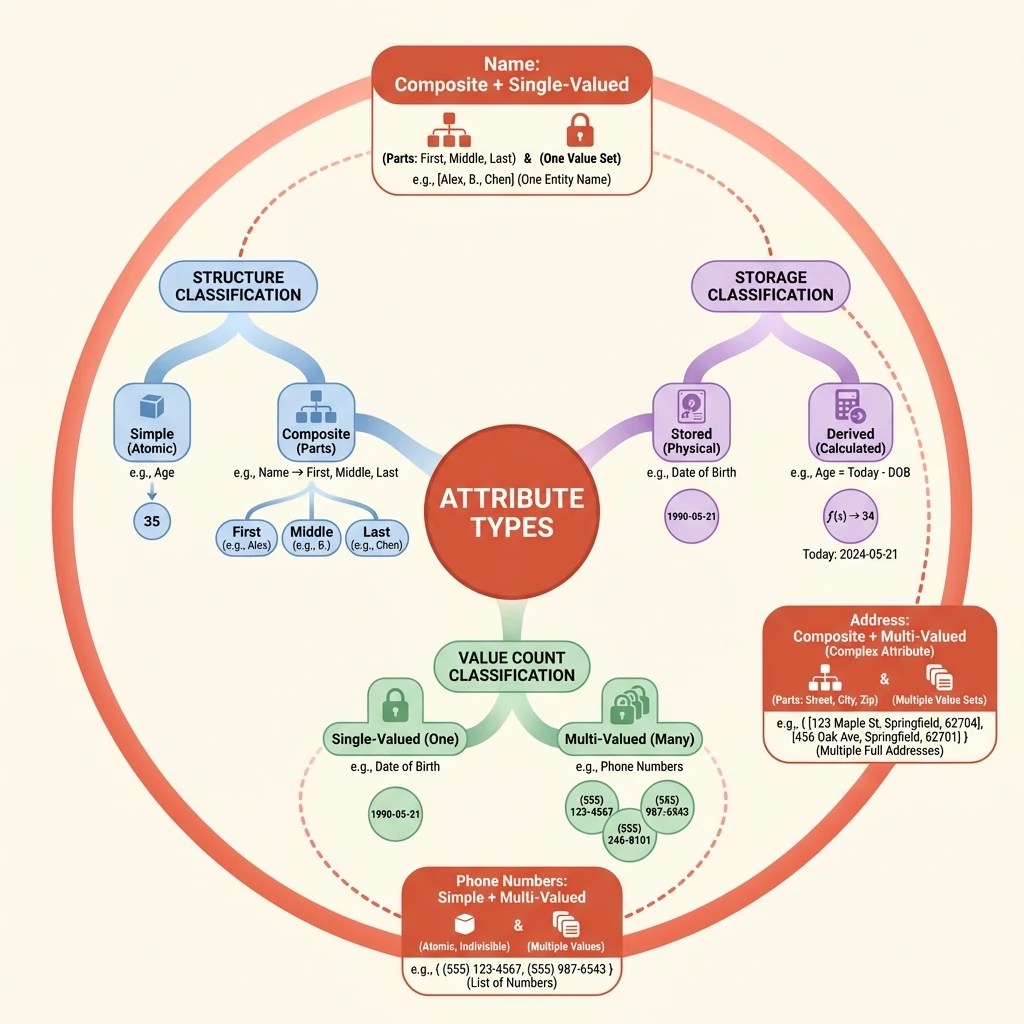
Simple and Composite: Structuring Atomic Information
Attributes can be examined by their internal structure. A simple attribute is indivisible; it represents an atomic piece of information. In contrast, a composite attribute can be broken down into smaller, meaningful component parts. The decision between simple and composite modeling hinges on whether the attribute's parts are meaningful for querying and organization.
For example, modeling a trainee's name as a single "Name" string is a simple attribute. However, if the system needs to address letters formally (using a last name) or sort records alphabetically by surname, then 'Name' becomes a composite attribute composed of 'First Name', 'Middle Name', and 'Last Name'. This composite structure provides better data organization by isolating the components you are most likely to query independently.
Single and Multi-Valued: Cardinality of Facts
Another critical axis is how many values an attribute can hold for a single entity instance. A single-valued attribute can have only one value at a given time. A multi-valued attribute can have a set of values. This distinction is a key design decision that directly impacts storage and requires special handling in a relational model.
A trainee's age is inherently single-valued; you can only be one age at any moment. In contrast, attributes like 'Phone Number' or 'Email Address' are often multi-valued, as a single trainee may legitimately possess a home number, a mobile number, and a work number. The choice isn't always fixed by reality but by system requirements.
Stored and Derived: Avoiding Redundant Truths
Data integrity requires minimizing redundancy. A stored attribute's value is physically kept in the database. A derived attribute's value is not stored but is calculated from other stored data when needed. This design avoids potential inconsistency, as the derived value always reflects the current state of the stored data.
The classic example is 'Date of Birth' and 'Age'. The date of birth is stored. The age is derived by subtracting that stored date from the current date. Storing age separately would introduce risk—the age would become incorrect the moment the trainee's birthday passes unless it was constantly updated. By deriving it, we maintain a single source of truth.
Complex Attributes: Combining Structures
Real-world data often requires combining these classifications. A complex attribute is an attribute that is both composite and multi-valued. It represents a collection of items, where each item itself has internal structure.
Consider a 'Phone Number' for a trainee in an international context. First, it is multi-valued (a trainee has more than one number). Second, each individual phone number could be modeled as a composite attribute, composed of a country code, an area code, and the local number. Recognizing complex attributes is essential for accurately modeling such nested, repeating data structures.
Key Insight
Attribute classifications (simple/composite, single/multi-valued, stored/derived) are not mutually exclusive. A single attribute must be analyzed across all dimensions to determine the optimal model.
Interactive Demonstration
🎯 Attribute Classifier
Conclusion
The Entity-Relationship model provides a powerful visual language for capturing database requirements. In this article, we covered:
- Entities — The real-world objects we want to track (Trainee, Course, Vehicle)
- Attributes — The properties that describe entities, classified across three
axes:
- Structure: Simple vs Composite
- Cardinality: Single-valued vs Multi-valued
- Storage: Stored vs Derived
- Relationships — The associations that connect entities into a coherent model
This conceptual foundation isn't just academic—it's the actual process used by database designers worldwide. Before writing a single line of SQL, they sketch ER diagrams to ensure all stakeholders agree on what the system should represent.
Looking ahead: With entities and attributes understood, we're ready to explore more complex relationship constraints—cardinality ratios, participation constraints, and the subtle differences between total and partial participation.